Handset Functions
Before operating the bed ensure that all safety notices have been observed and that safety checks have been made.
SAFETY NOTICE
The Handset Control is a “press” button operation.
To “operate” the bed, press the required function button and hold pressed till the required position of the bed is achieved.
To “STOP” the operation of the bed, release the button.
ENSURE ALLWHEELS ARE LOCKED BEFORE OPERATION
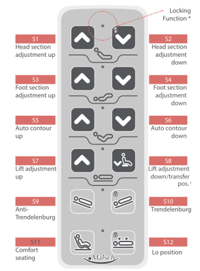
*To activate the locking function, place the magnetic chip supplied in the area marked red. At the same time, press the respective blocking button (for secondary symbols, see table). A red lighted LED in the middle of the row of buttons confirms that the function has been locked. This will disable the handset control and therefore all movement functionality of the bed.
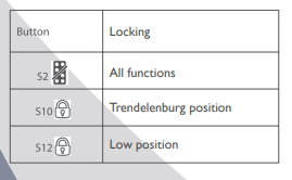
The locked functions are released in the same way. By placing the magnetic chip and simultaneously pressing the button with the lock symbol, the function is released again and the respective LED goes out.
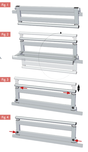
Adjust side rails
1 . In standby position, the side rails are located next to the sleeping surface. In this position, they prevent the mattress from slipping. (Fig. 1)
2. The side rails are raised by swivelling them upwards. In the middle position, they prevent the resident from falling out of bed.When raised at the head end, they also provide standing and mobility assistance for the resident. (Fig. 2)
3. The upright side rail is released by means of two spring catches in the side bars below the height adjustment handrail and positioned at its maximum height. Perform telescopic adjustments using both hands simultaneously when moving the rail upwards or downwards to prevent jamming. (Fig. 3) Do not force the movement!
4. To lower the telescoping side rail height extension, proceed the same way as to raise it.
5. To swivel the side rails back to the standby position, press the indicated latches on the lower side rail bar inwards simultaneously and initiate the tilting motion. (Fig. 4)
Caution
When raising the side rails and side rail height extensions, ensure and check that the latches engage securely. Always use both hands to move this element!
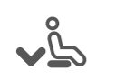
Activate the low position on the IMPULSE care bed with undercarriage Edition 400 with retracted side rails! (Fig.1)

You can move the lower leg section into a horizontal position (extended leg elevation) using the adjustable notched bracket.
Auto Contour
Please consider resident safety when adjusting the auto contour! Ensure that no body parts or any objects are located in the area of the lifting mechanism.
Use the corresponding buttons on the hand controller to adjust the auto contour.

Using the button function adjusts the back rest and upper leg section equally.
This function must only be used with mobile residents and residents without any physical problems.
Height Adjustment
Use the corresponding buttons on the hand controller to adjust the height.
Please consider resident safety when adjusting the height. Ensure that no body parts or any objects are located in the area of the lifting mechanism.